 Adding sockets, loops, and terminators
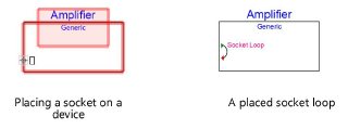
A socket is a port on a device through which a signal flows. Devices can incorporate any number of input, output, or input/output (I/O) sockets. Since signals typically flow from left to right, place input sockets on the left side of a device and output sockets on the right. Sockets can be named based on the type of connector and the signal they carry, or by a custom naming convention. While sockets can be placed on the top side of a device, that area is normally reserved for the device name label.
A socket loop places three objects: a socket, an adjacent socket, and a loop on the same device (creating a “loop-thru”). If adjacent input or bi-directional sockets are already present, the Socket Loop tool connects them with a loop. Multiple loop-thrus can be connected in a chain, to send the same signal to several locations.
The Terminator tool adds or removes a terminator. Terminal sockets cannot be connected.
Adding sockets and socket loops
|
Tool |
Tool set |
|
Socket
Socket Loop
|
Schematics |
![]()
|
Mode |
Description |
|
Single Click
|
Places a single socket or socket loop at the click location |
|
Linear Array
|
Places an array of sockets or socket loops along the drawn line |
|
Name |
Enter the name that appears in various worksheets; names must be unique. If placing an array of sockets, a number is automatically appended to the name. |
|
Input/ Output/ Bi-Directional
|
Select whether the socket is type is IN, I/O, or OUT. This setting determines how the Connect tool draws circuits. Socket loops are IN or IN/OUT only. |
|
Left/ Right/ Top/Bottom |
Specifies the orientation of the socket or socket loop |
|
Automatic Type
|
Automatically places the socket or socket loop in the correct orientation, based on where it goes on the device. The automatic detection works best for standard rectangular device shapes. |
|
Signal |
Select the type of audio, video, communication, networking, computer, phone, or provider signal; select --- to indicate a passive socket, or select ??? for an unknown type of signal |
|
Connector |
Select the type of connection; select --- to indicate that there is no connector, or select ??? for an unknown type of connection |
To place sockets:
Click the tool, and select the placement mode.
Select Input, Output (socket only), or Bi-Directional (I/O) mode.
Click the mode that matches the orientation for the socket or loop; alternatively, select Automatic Type mode to automatically select the orientation as the object is placed on a device.
Select the Signal category and type; the Connector is automatically selected, but it can be changed.
Click to place the socket or socket loop into the drawing, normally on a device.
If placing the socket on an existing device, the device is highlighted and the socket or socket loop automatically becomes part of the device.
In Single Click mode, click once to place the object.
In Linear Array mode, click once to start the array; move the cursor to set the distance and direction of the linear array. Press the Shift key to constrain to the horizontal or vertical direction. The preview indicates the spacing and placement of the objects; the floating Data bar shows the Count. Click to place them.
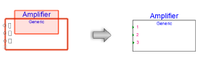
In addition to label information, the socket’s appearance indicates whether it is an output socket (red triangle), input socket (green triangle), or bi-directional socket (both red and green triangles). Socket appearance can be changed; see Editing devices and sockets.
The socket parameters can be edited later from the Object Info palette.
To edit sockets and socket loops that are part of a device, select Modify > Edit Device. A colored border around the drawing window indicates that you are in an editing mode, where the sockets can be edited. The Exit Device command becomes available from the Modify menu, and the Exit Device button is visible in the top right corner of the drawing window.
The Connections Count parameter, which displays the number of connected circuits, is available for worksheets (see Creating worksheets), record formats (for displaying text linked to a record, see Linking text to record formats), and data visualizations (see Creating a new data visualization).
Click to show/hide the parameters.Click to show/hide the parameters.
|
Parameter |
Description |
|
General |
|
|
Type |
Select whether the socket is type is IN, I/O, or OUT. This setting determines how the Connect tool draws circuits. |
|
Socket Name |
Enter the name that appears in various worksheets; socket names must be unique |
|
Display Tag |
Enter the name that displays on the drawing; this can be a shorter name to save space on the drawing |
|
Signal |
Select the type of audio, video, communication, networking, computer, phone, or provider signal; select --- to indicate a passive socket, or select ??? for an unknown type of signal. The selected signal type displays below the list. |
|
Connector on Cable |
Select the type of connection; select --- to indicate that there is no connector, or select ??? for an unknown type of connection. The selected connection type displays below the list. |
|
Number of Circuits |
Normally, use a value of 1 unless the socket is a multi-circuit socket; enter the number of circuits |
|
Orientation |
Displays the relative location of the socket graphics on the device, according to the selected tool |
|
Is Terminated |
Adds a terminator to the socket; a terminal socket cannot be connected to a circuit |
|
Advanced Customization |
The socket and its label automatically display in a style that matches the socket signal, text orientation, and connector type; this can be customized. The styles are resources that can be edited from the Resource Manager by the advanced user. |
|
Graphic Style |
Select a socket graphic style from the list |
|
Label Style |
Select a socket label style from the list |
If you plan to reuse the device in the future with its sockets and loops, click Save as Symbol from the Object Info palette of the selected device to save the device as a symbol definition resource.
Adding terminators
|
Tool |
Tool set |
|
Terminator
|
Schematics |

A socket with a terminator cannot be connected to a circuit.
To place a terminator on a socket:
Click the tool.
Add a terminator to a socket by clicking on the socket. Alternatively, select Is Terminated from the Object Info palette of a selected socket.
If an existing terminator is no longer needed, click on the terminator with the tool to remove it, or deselect Is Terminated.
